Semester: Spring 2025
Location: Syracuse, NY
Instructor: Elizabeth Kamell
Collaborator: Juinkye (Kyle) Chiang
Location: Syracuse, NY
Instructor: Elizabeth Kamell
Collaborator: Juinkye (Kyle) Chiang
FACADE
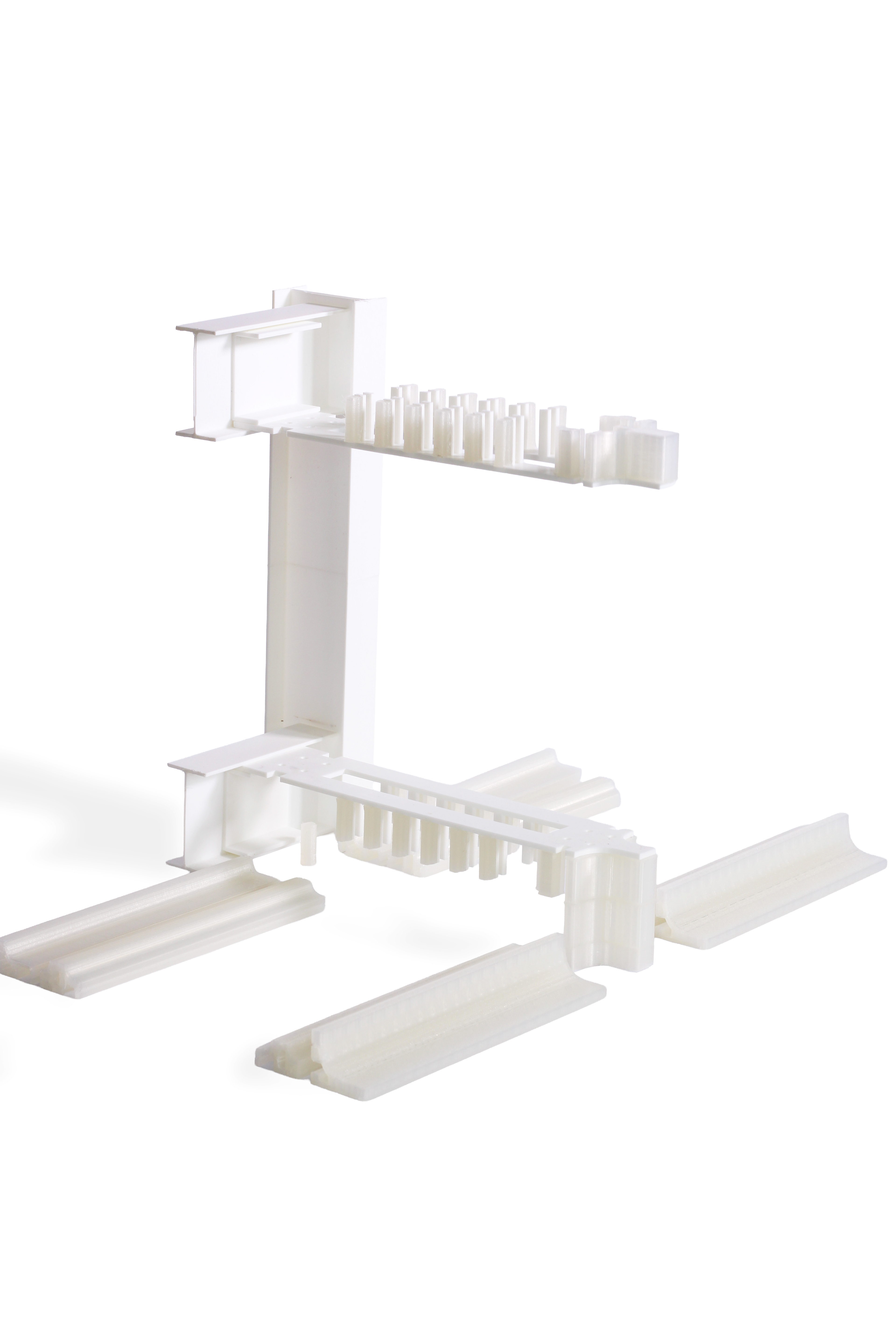
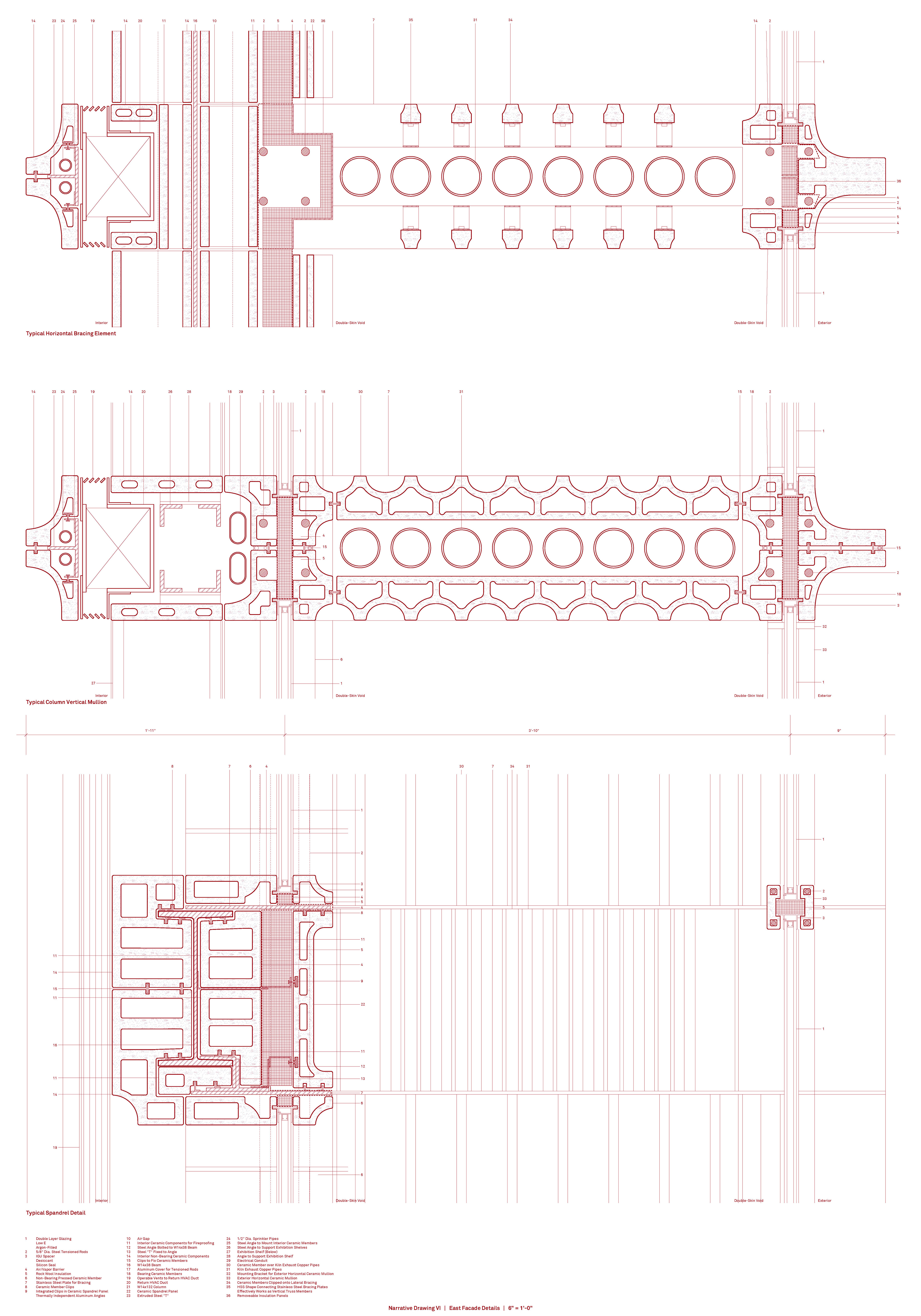
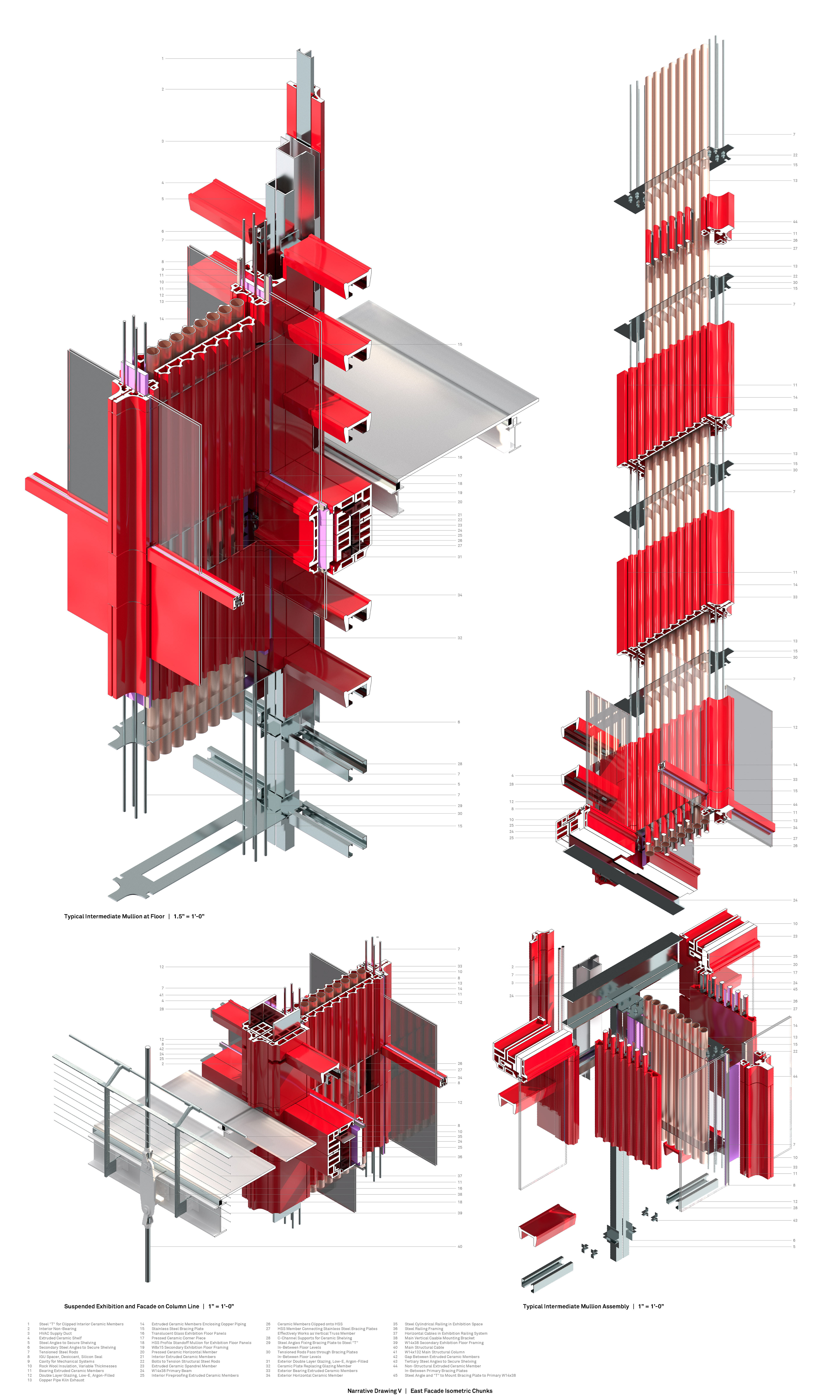
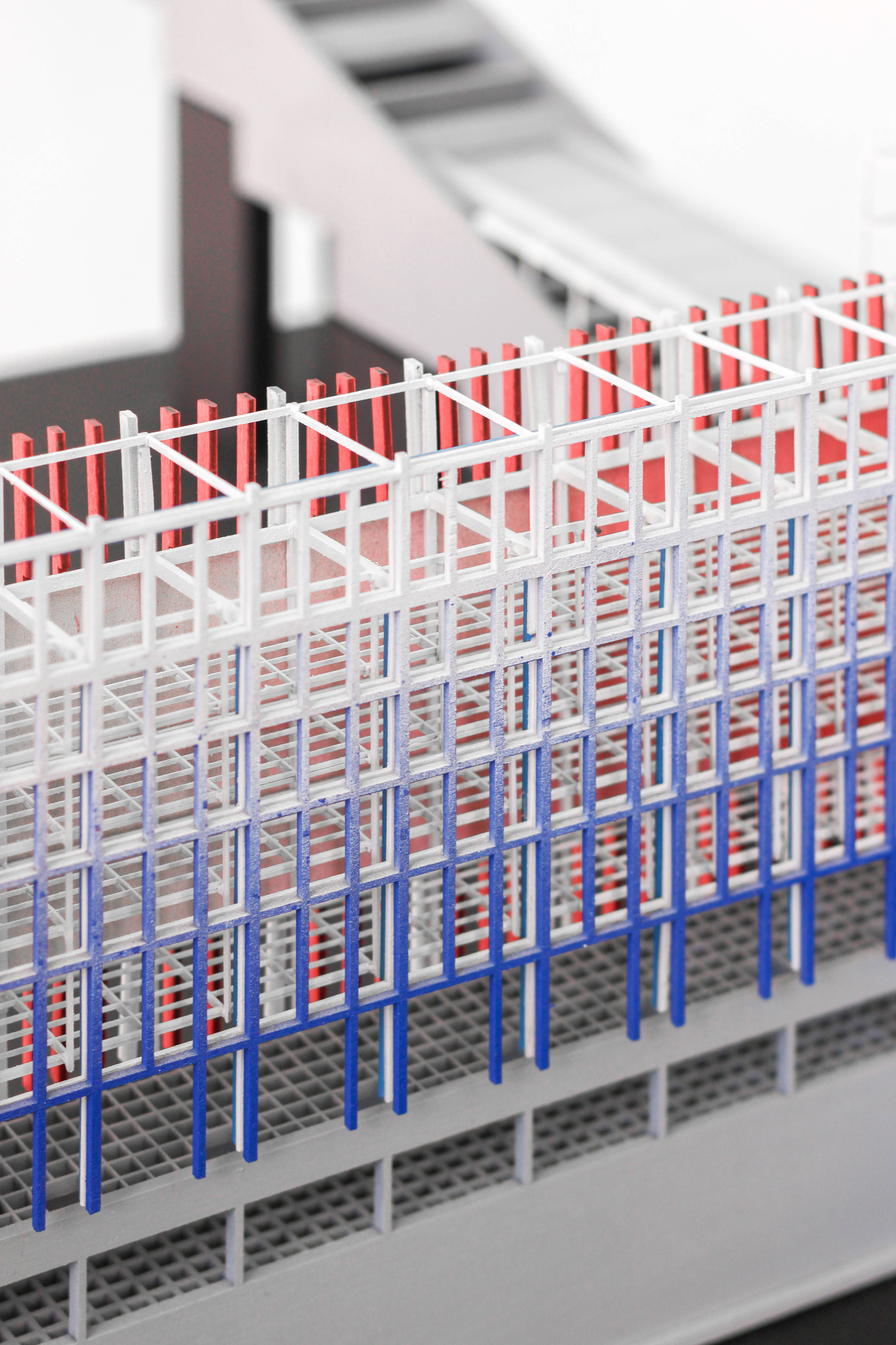
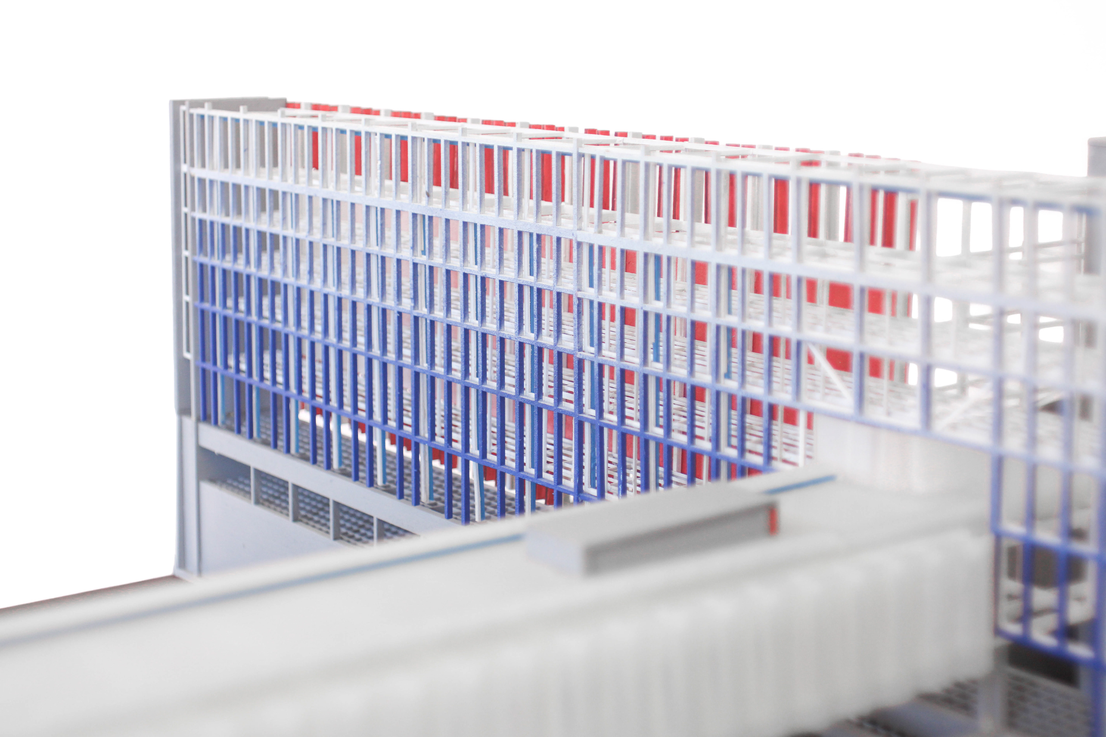
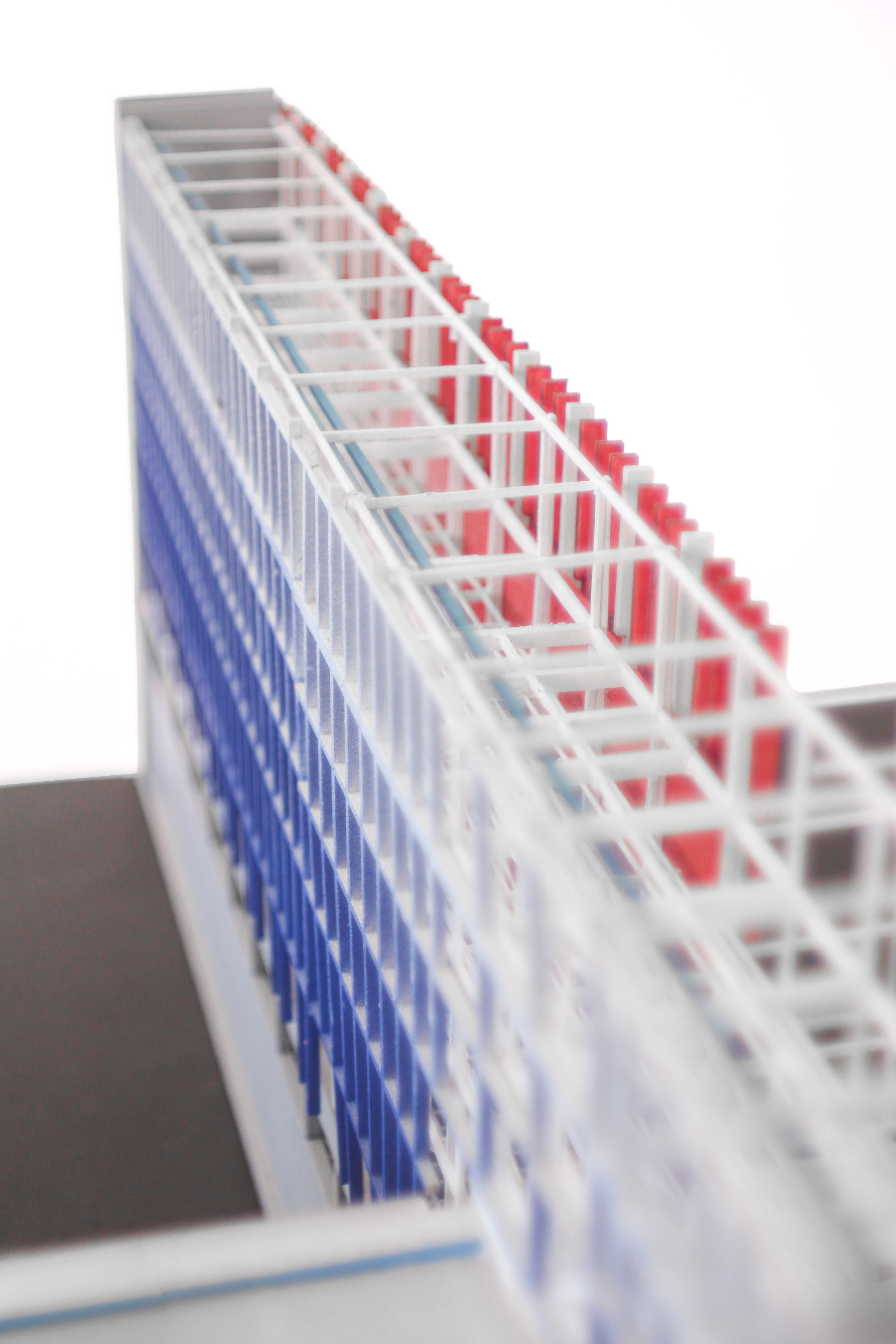
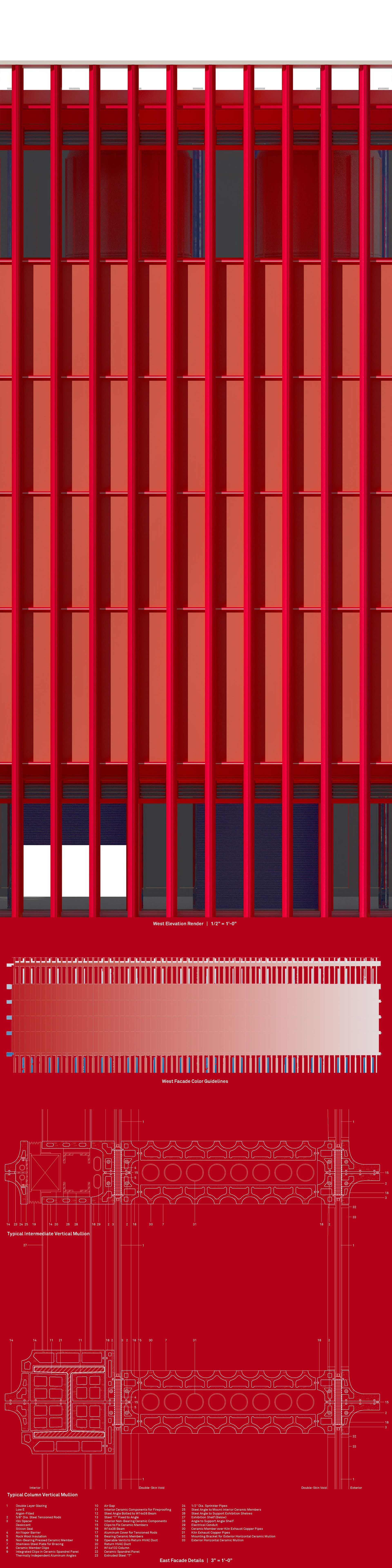
New enclosure technologies developed by John Neary as part of the 2021 ACAW Workshop promise methods to make curtain walls out of structural ceramic, held in compression by steel tension rods. This project adapts and modifies the ACAW prototype to clad the Exhibition Wall. Looking to late 19th-century ceramic fireproofing techniques, this cladding system integrates additional, yet essential, functions of fireproofing, interior finishing, vessel display, and mechanical chases. To the west, the facade acts as a public exhibition – a wall that is art. To the east, the same system is adapted to form a double-skin enclosure, forming internal voids to carry and distribute heat from the kilns. To the interior, its flexible forms bend to create shelving for display in the galleries.
New enclosure technologies developed by John Neary as part of the 2021 ACAW Workshop promise methods to make curtain walls out of structural ceramic, held in compression by steel tension rods. This project adapts and modifies the ACAW prototype to clad the Exhibition Wall. Looking to late 19th-century ceramic fireproofing techniques, this cladding system integrates additional, yet essential, functions of fireproofing, interior finishing, vessel display, and mechanical chases. To the west, the facade acts as a public exhibition – a wall that is art. To the east, the same system is adapted to form a double-skin enclosure, forming internal voids to carry and distribute heat from the kilns. To the interior, its flexible forms bend to create shelving for display in the galleries.
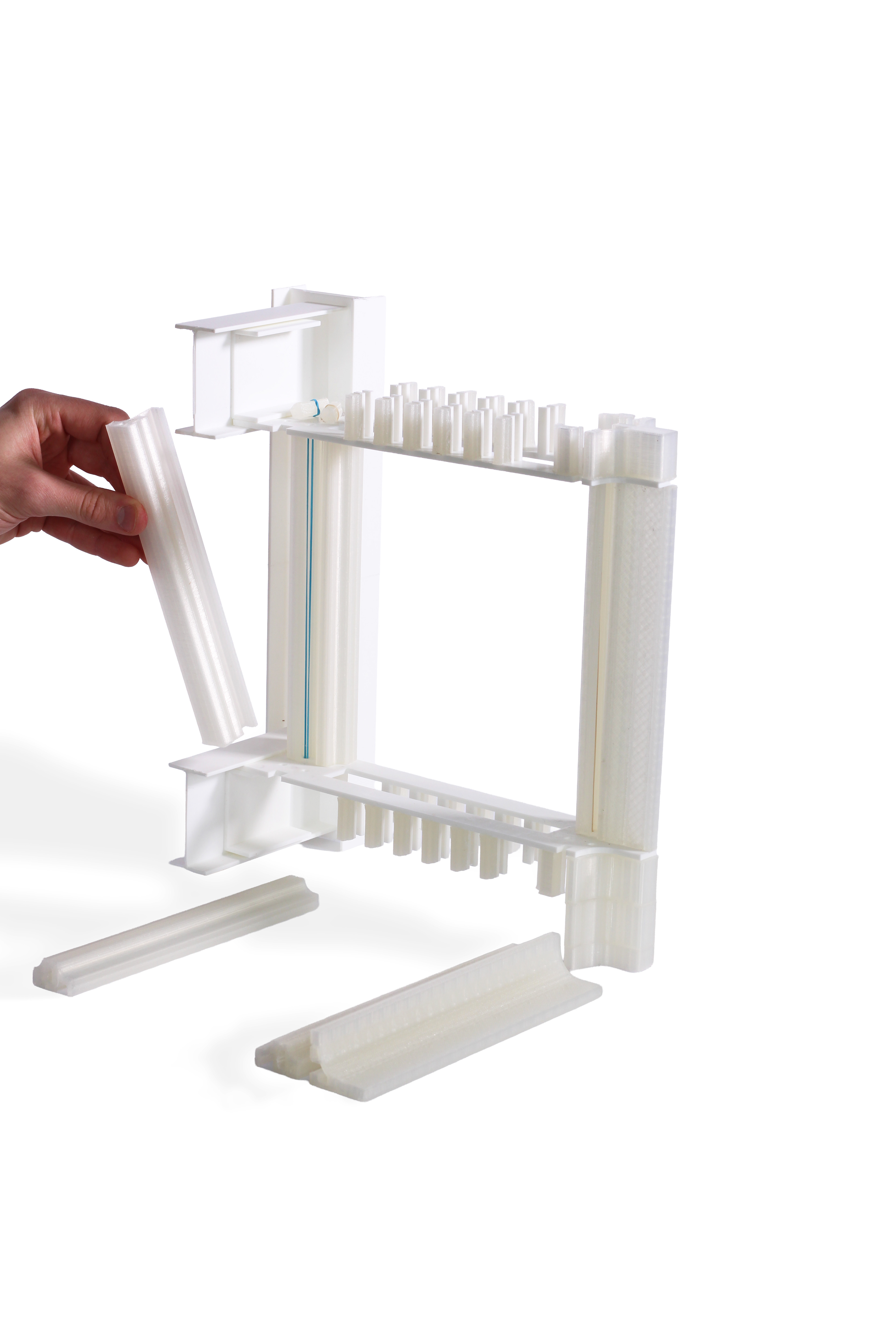
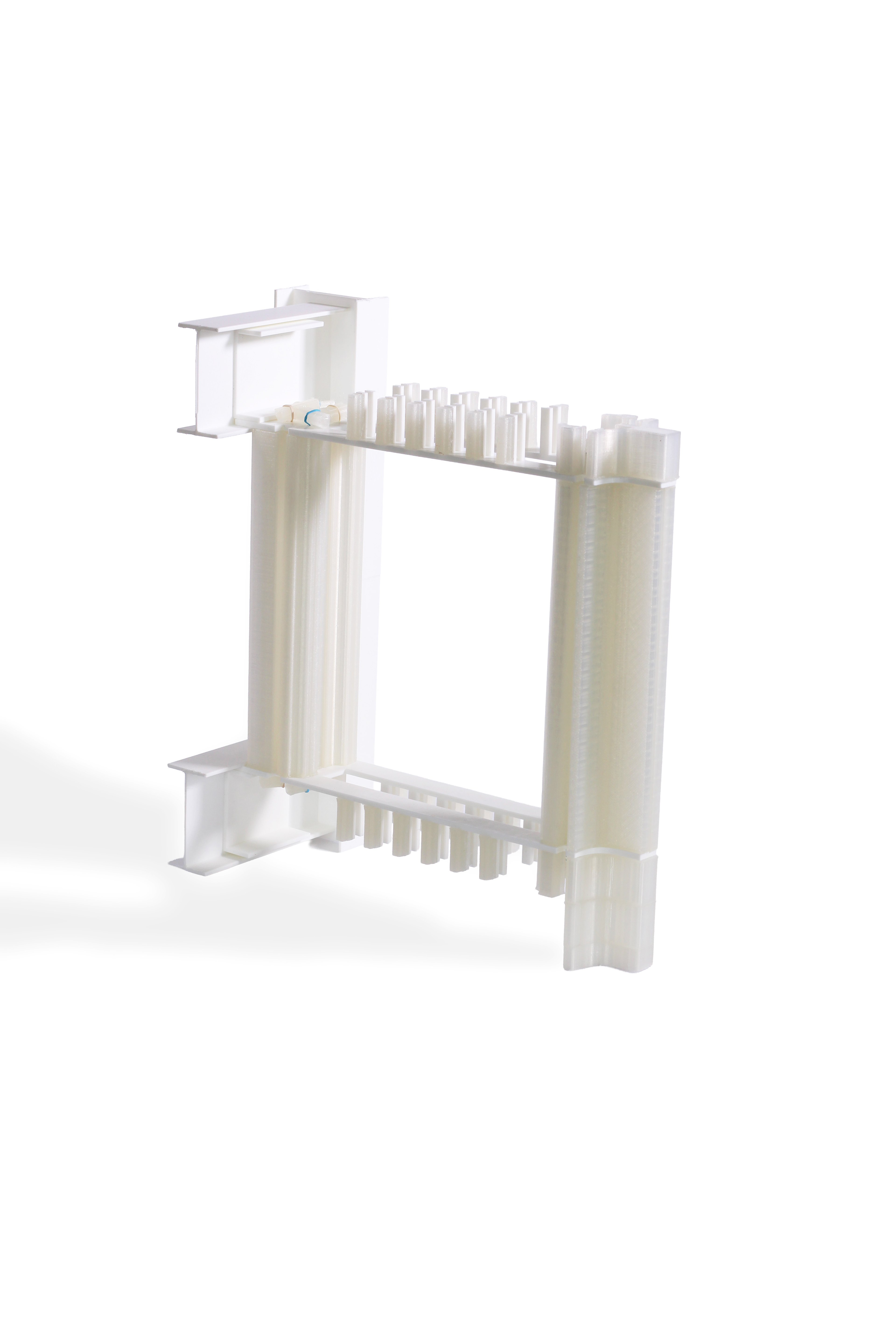
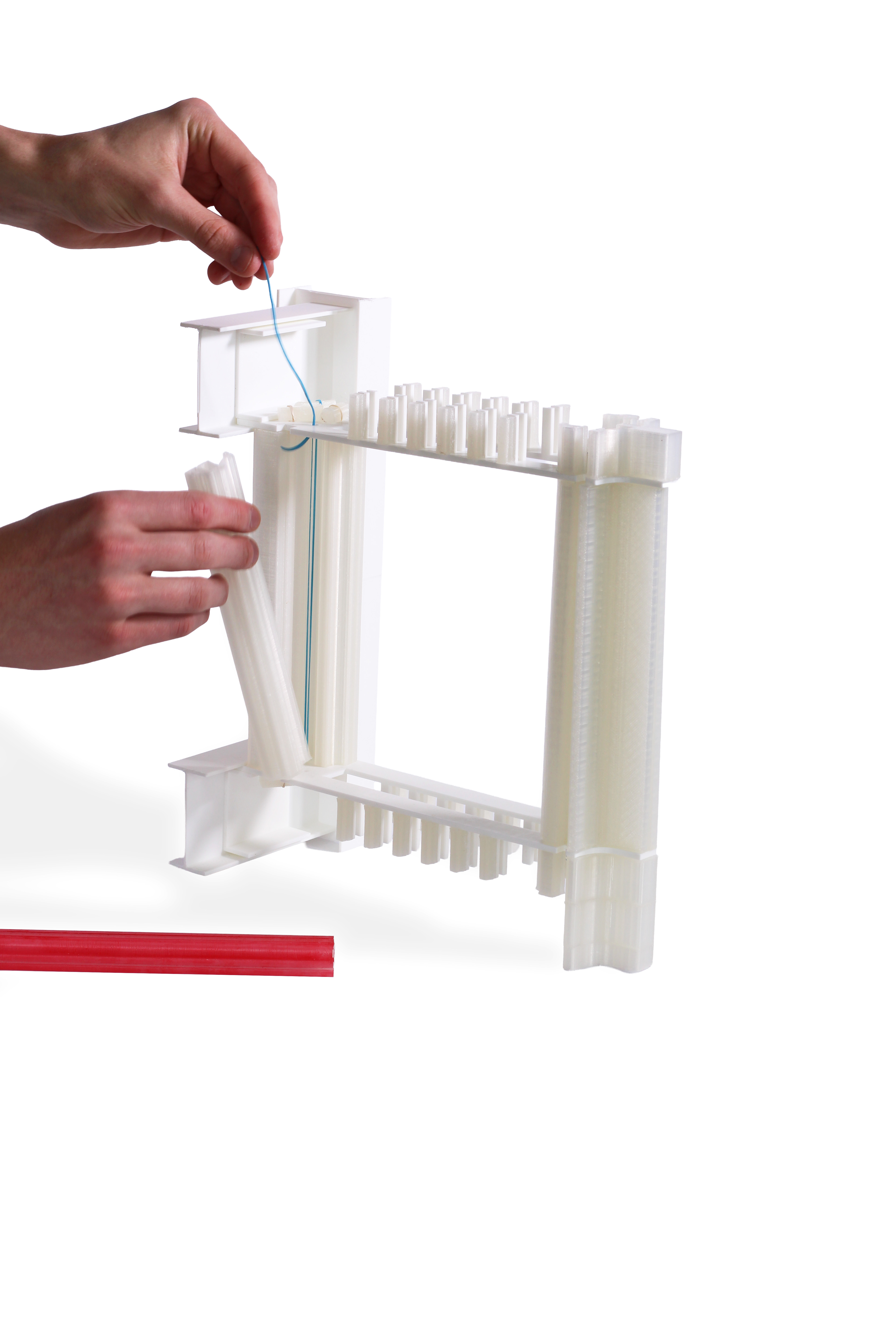
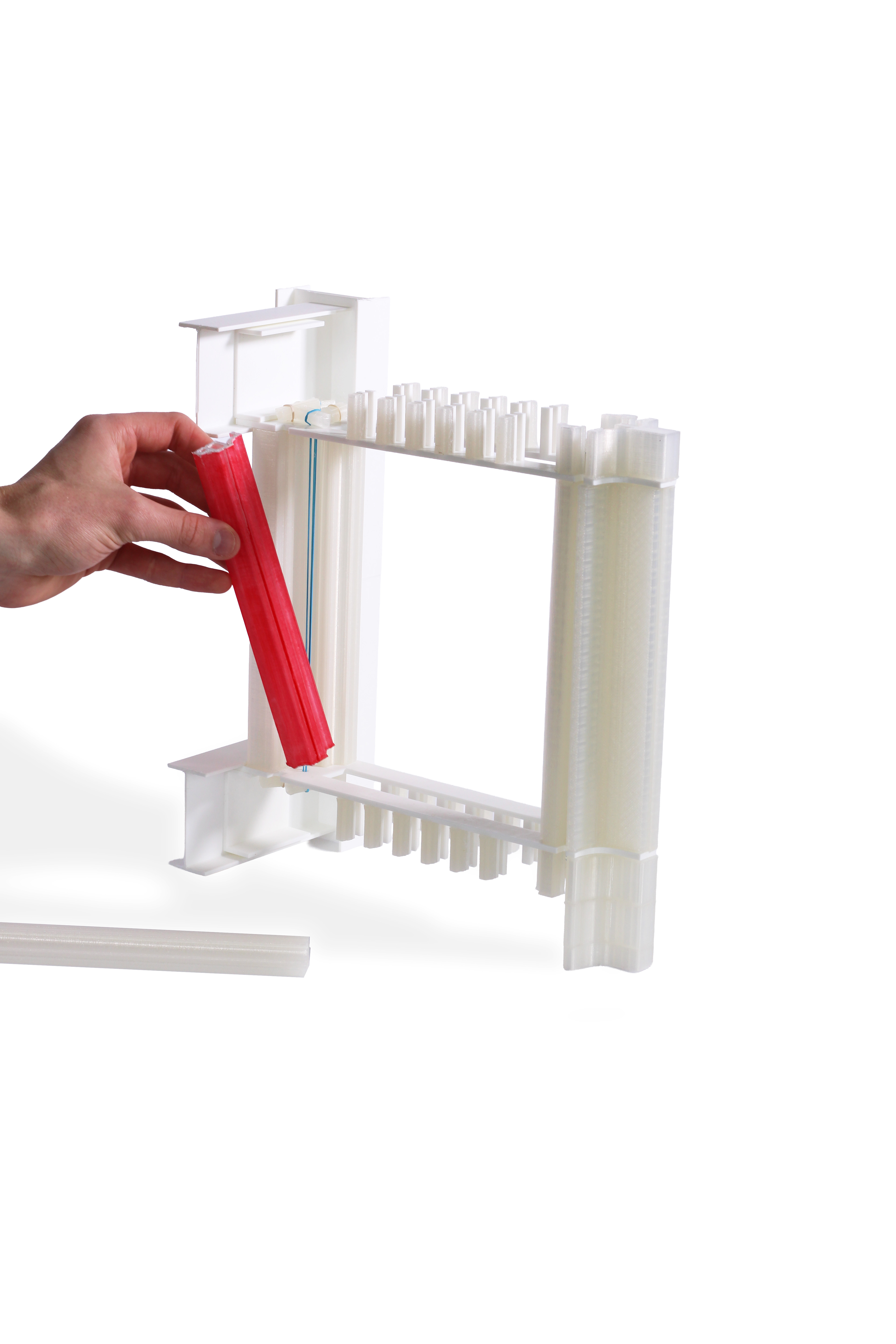
By holding the ceramic members in compression through tensioned steel rods, represented as rubber bands in the model below, selective loosening allows for individual pieces to be removed and replaced as needed. By having four rods in each cluster, the system incorporates redundancy, becoming resilient against the failure of any individual rod. Opposed to contemporary, layered enclosure systems, this new enclosure removes climate-intensive and thermal-bridging formed aluminum members from the fabrication process and replaces them with sustainable, simply-extruded ceramic alternatives.
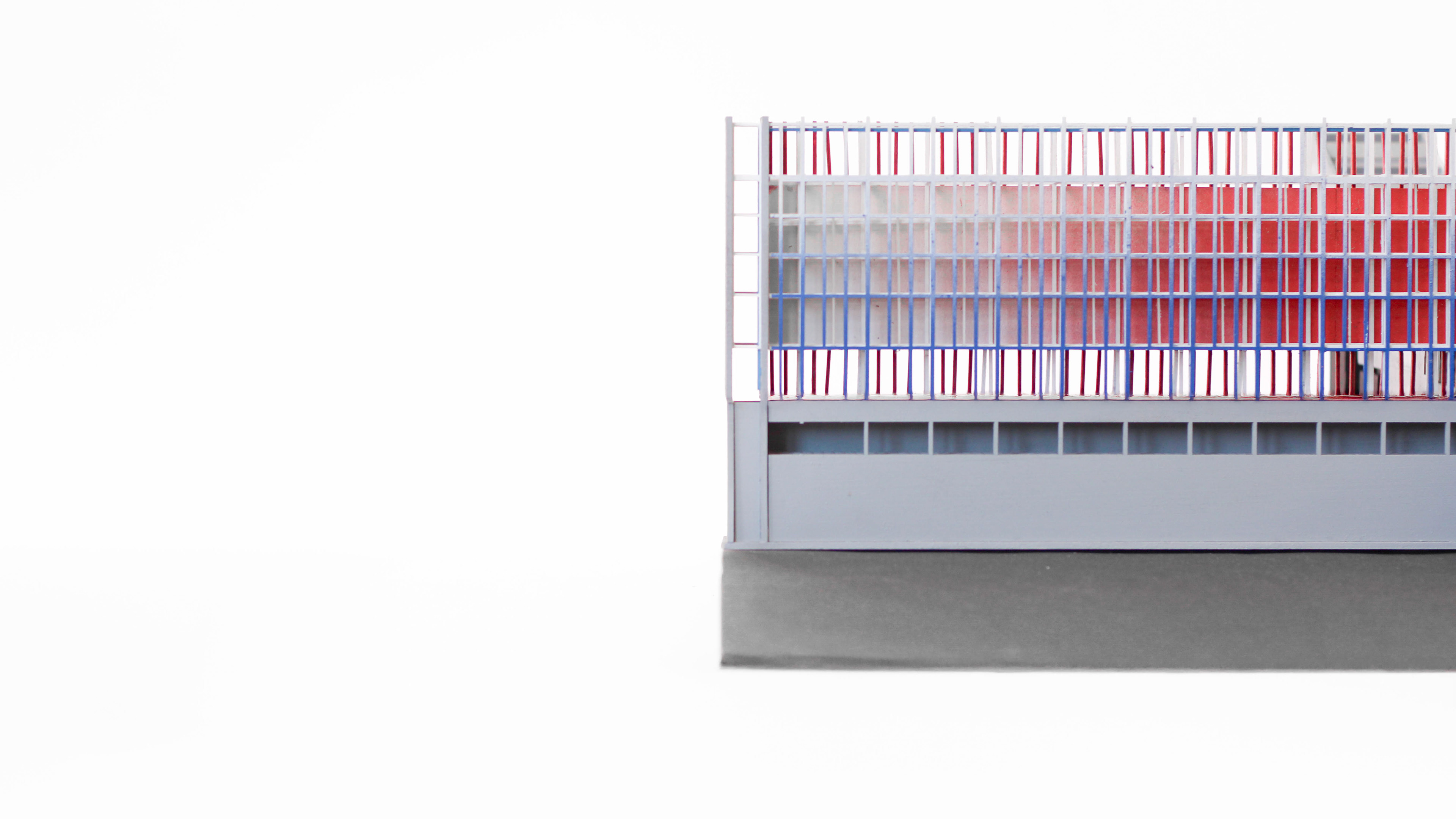
Pedagogically, this facade system serves to teach the ComArt students about the applications of the ceramic arts beyond vessels and figures. The facade is not an industrially-produced monolith, but a form produced and changed by the students and faculty. Formed from simple clay extrusions, classes would take part in the initial design, forming, and glazing of these members, and as they are damaged or wear out, students would be the ones to replace them.
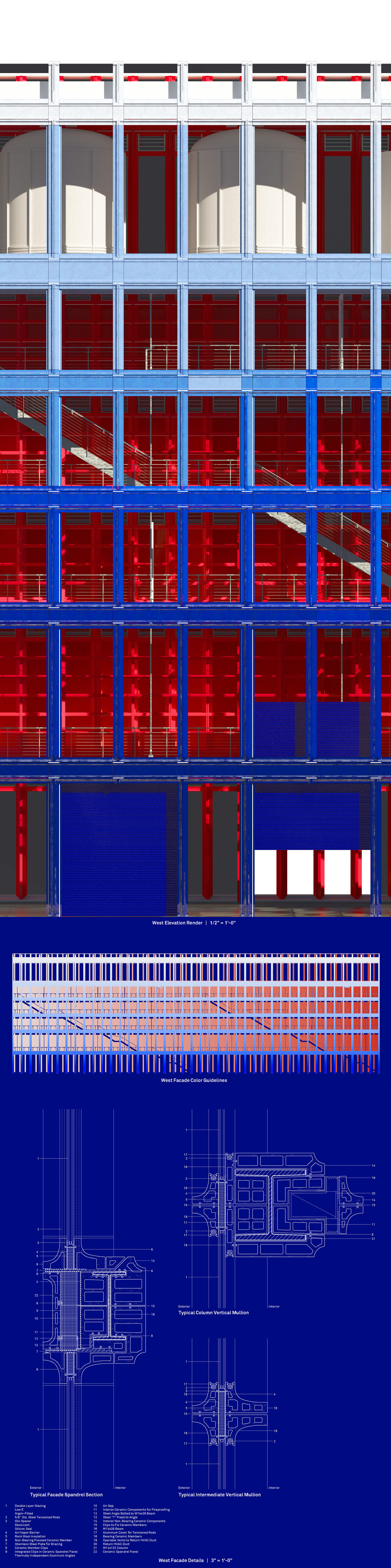
In order to maintain clarity between the many hands that would form these facades, this project worked through a series of color gradients (blue and red). When mapped onto the elevations, they provide rough indications to each student on the hue and saturation of their assigned piece. It is up to the students’ discretion to work with this information in the production of their ceramic member.
As such, this machine – this shaper of material – this manipulator of flows – this form of production – this space of process – grows beyond its role as a simple machine. It incorporates a rigorous detailing methodology to produce, reinforce, and project a new pedagogy for ceramics in art and architecture, and integrates this pedagogy in both form and flow, working across materials, forces, and users.
The machine clads itself.
MECHANICAL SYSTEMS
This project utilizes a series of both passive and active systems to heat, cool, and ventilate its spaces in accordance with its ideas of redundancy and multi-layered systems.
This project utilizes a series of both passive and active systems to heat, cool, and ventilate its spaces in accordance with its ideas of redundancy and multi-layered systems.
Heat
While the primary heating comes from the university-operated steam plant (which already provides steam to most campus buildings), the kilns and 100-foot-deep vertical geothermal piles combine to form alternative, sustainable heat sources. The kilns are exhausted directly into the East facade, where the heat is trapped between the double-skin enclosure. During the winter, this provides a buffer between interior and exterior and filters into the exhibition space through operable louvers. Geothermal piles are used to heat water to an intermediate temperature of ~56°F, which through a heat exchanger controls the interior environment through radiant hydronic loops.
While the primary heating comes from the university-operated steam plant (which already provides steam to most campus buildings), the kilns and 100-foot-deep vertical geothermal piles combine to form alternative, sustainable heat sources. The kilns are exhausted directly into the East facade, where the heat is trapped between the double-skin enclosure. During the winter, this provides a buffer between interior and exterior and filters into the exhibition space through operable louvers. Geothermal piles are used to heat water to an intermediate temperature of ~56°F, which through a heat exchanger controls the interior environment through radiant hydronic loops.
Ventilation
In the summer, the same heat produced by the kilns and stored in the double-skin East facade is used to drive stack-effect ventilation. Large doors on the bottom of the West facade, along with operable dampers on higher floors, facilitate a controlled intake of air. This air is drawn through the Exhibition Wall and into the double skin through an additional set of dampers on the opposite side. Due to the high temperature of the double-skin air and the negative pressure on the eastern side of the building, based on prevailing western winds, a constant flow of air out of the east facade will be supported, driving air movement throughout the rest of the Exhibition Wall. In the Process Bar, a similar effect is achieved through active fans and a double-skin glass facade. In the winter, the louvers are closed to retain an air barrier and conserve heat. In the summer, the fans actively draw air through the double-skin. Interior operable windows can direct the air into the Bar volume. Windows on the opposite North facade facilitate cross-ventilation.
In the summer, the same heat produced by the kilns and stored in the double-skin East facade is used to drive stack-effect ventilation. Large doors on the bottom of the West facade, along with operable dampers on higher floors, facilitate a controlled intake of air. This air is drawn through the Exhibition Wall and into the double skin through an additional set of dampers on the opposite side. Due to the high temperature of the double-skin air and the negative pressure on the eastern side of the building, based on prevailing western winds, a constant flow of air out of the east facade will be supported, driving air movement throughout the rest of the Exhibition Wall. In the Process Bar, a similar effect is achieved through active fans and a double-skin glass facade. In the winter, the louvers are closed to retain an air barrier and conserve heat. In the summer, the fans actively draw air through the double-skin. Interior operable windows can direct the air into the Bar volume. Windows on the opposite North facade facilitate cross-ventilation.
HVAC
HVAC is used for both the climate-controlled Bar volumes and the Exhibition Wall because it is more effective at maintaining the precise temperature and humidity controls ceramics require. In the Process Bar, supply ducts run in the center of the floor under the structural box-truss members. They supply the space via risers between structural members and are served by air handling units in the concrete circulation pillars. In the open working spaces, the forced air enters through floor diffusers, but in the climate-controlled drying and cooling volumes, it enters through the CMU walls. Return ducts are integrated in railings on the roof of the Process Bar, defining boundaries for the exhibition/green roof above while providing a void for return and exhaust.
HVAC is used for both the climate-controlled Bar volumes and the Exhibition Wall because it is more effective at maintaining the precise temperature and humidity controls ceramics require. In the Process Bar, supply ducts run in the center of the floor under the structural box-truss members. They supply the space via risers between structural members and are served by air handling units in the concrete circulation pillars. In the open working spaces, the forced air enters through floor diffusers, but in the climate-controlled drying and cooling volumes, it enters through the CMU walls. Return ducts are integrated in railings on the roof of the Process Bar, defining boundaries for the exhibition/green roof above while providing a void for return and exhaust.
In the Exhibition Wall, supply ducts are integrated into the eastern facade, running through the thickened mullions (see details below). Return ducts are similarly integrated into the western facade, allowing for controlled air flow throughout each level.
Radiant Heating
To the eastern end of the bar, both at grade and as the structure is caught by the hillside, research spaces with longer and more regular occupation timings are serviced by radiant heating. For similar reasons, the system continues into studio spaces in the Bar with higher occupation rates. Heat is provided from both geothermal and university-operated steam sources, and works through multiple heat exchangers to create different heating zones. Spaced 12” apart, the PEX tubing is placed within a 4” concrete cover on the floors of each research and studio space.
To the eastern end of the bar, both at grade and as the structure is caught by the hillside, research spaces with longer and more regular occupation timings are serviced by radiant heating. For similar reasons, the system continues into studio spaces in the Bar with higher occupation rates. Heat is provided from both geothermal and university-operated steam sources, and works through multiple heat exchangers to create different heating zones. Spaced 12” apart, the PEX tubing is placed within a 4” concrete cover on the floors of each research and studio space.